Tuesday, June 5, 2012

Michael Barr - Embedded C Coding Standard - Review

  Hello there!
  This post is a review of Michael Barr's Embedded C Coding Standard book.
  First of all, why a c coding standard? I have been working in my life in small and medium companies and in most of them, we always had the same problem. No c coding standard. Everyone had their own standard and very often, those standard are not standard, because it used to change every project. Every time some one quit the company, it's always the same problem: code badly written, no comments, hard to read, hard to understand and overall hard to maintain.
  So this book is a very good start point for those who works in a company which doesn't have a standard and want to deploy one.
  First Michael Barr make clear that the code written is a property of the company and not of the programmer. A standard code eliminates conflict over items that are sometimes viewed as personal stylistic preferences.
  Yet, a standard can prevent some bugs because it forces a programmer to follow some good practices that people normally doesn't do, like always open and close braces, even in a if with only one statement.
  Indeed, this book shows some goods practices like:

  1. Never leave a code with comments. We should comment code with #if 0
  2. Use inline functions instead of macros
  3. Always use parentheses and don't rely in C's operator precedence
  4. Use of doxygen to document code
  5. Create the comments before begins to code once we have to know what the functions must do before start coding.
  Of course there are some suggestions that I'm not agree like:
  • Use only 80 columns for code
  I think that nowadays we have big screens and the IDE is much better than before, so I don't see any problem in use more than 80 columns.
  • Use goto, continue or break.
I understand that the use of this keywords can lead to "spaguetti" code, but if you really  know what are you doing, I don't think that you'll have problems.
  We can always adapt this standard. The most important thing is to have one and follow it. For sure it will save you several hours of debugging and it will improve your code quality.

  Marcelo
Read more ►

Thursday, May 10, 2012

FPGA hello world - Led blink - Part III

  Hello everybody!
 As promissed a century ago, in this post I'll show how to assign pins to our FPGA hello world, aka Led blink, how to generate our bitstream and how to program our FPGA. So let's do it!
  We have two choices:

  1) In menu Tools/PlanAhead - Pre-synthesis or
  2) In the design windows, in User Constraints, just double click in I/O Pin Planning (PlanAhead) - Pre-synthesis In both cases, it will ask you to create an UCF file. Accept it by clicking Yes.


  You'll note a new file helloworld.ucf, double clicking it will open PlanAhead. We can see all ports that we have declared before:
  led(8) - output
  clk - input
  updown - input

  Now it's time to assign pins to signals. In this board we have:

  Led 0 - R14
  Led 1 - C3
  Led 2 - E6
  Led 3 - D6
  Led 4 - D13
  Led 5 - A7
  Led 6 - G9
  Led 7 - A8
  clock - C9
  updown - L13 (switch SW0)

  Here we can see in PlanAhead all pins assigned.


  Note that we have again two options. Using PlanAhead we can click in the Site column and chose which pin to use or ISE, double click in Edit Constraints (Text) and type all constraints. Normally I assing one by PlanAhead and copy the rest in text mode which I think is faster.
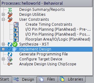
  Once done we can implement our design by clicking in Implement Design at Design tab in ISE.


  Now it's time to generate our programming file by clicking in Generate Programming File (durrr). Once done, we click in Configure Target Device which will opens Impact. It will ask you to create a new project file, just click Yes.
  Go to menu Edit/Launch Wizard. Select Configure devices using Boundary-Scan (JTAG) and select our helloworld.bit file. Bypass all 3 others devices. In the next window, check Pulse PROG, click in Apply and OK.


  In the image above we can see that our FPGA is assigned with helloworld.bit and the others 3 device were bypassed. Now right-click over the green FPGA and select Program.
  And it's done! (I really wish that your leds are blinking!!! LOL)
  
  Marcelo


Read more ►

FPGA hello world - Led blink - Part II

  Hello!
  In this post I'll show you how to simulate our hello world design.
  In ISE, in Design tab, select View Simulation as in the image below


  Now we "compile" our design as usual. First we select in Hierarchy our helloworld entity and click first in Behavioral Check Syntax and then Simulate Behavioral Model.


  After click in Simulate, a new program will be launch - ISim.We'll have all signals defined in our design there.

  We select all signals and we add them to wave window. We can drag and drop them or right clicking all selected signals and selection Add to wave window.
  We need to create our clock signal by right-clicking in clk signal and selecting Force Clock. In our case 50MHz has a 20ns period. We set our updown to 0 first and then to 1 to see what happens. Here I also changed blink_freq to 1000000 to be able to show you the results (1 Hz is an eternity for our FPGA). Click in run and that's it!


   We can see that we're decreasing our led value when updown = 0 and increasing when updown = 1. The updown value changes in the blue cursor.

  Next post, I'll show how to configurate our FPGA and finally see our leds blink!

 Bye
 Marcelo
Read more ►

Sunday, January 15, 2012

FPGA hello world - Led blink

  Hello guys!
  Let's do our first design using the demo board.

  I'll explain step-by-step how to create a new project, develop our code and synthesize it using ISE 13.3 installed in the last post.

  1) First we have to create a project.Go to File > New Project...
      Name: helloworld
      Top-level source type: HDL

  2) Then we have to select device
      Family: Spartan3E
      Device: XC3S1600E
      Package: FG320
      Speed: -4
      Simulator: Isim(VHDL/Verilog)
      Preferred Language: VHDL
      VHDL Source Analysis Standard: VHDL-200X

  3) Now at panel left "Design", right click over : xc3s1600e-4fg320 and select "New source..."
  4) Select "VHDL module" and type filename: helloworld.
  5) We don't need to enter right now the port name. We can define after in the code. Click NEXT and then FINISH.

  Now we can start make some code:

library IEEE;
use IEEE.STD_LOGIC_1164.ALL;

-- Uncomment the following library declaration if using
-- arithmetic functions with Signed or Unsigned values
use IEEE.NUMERIC_STD.ALL;

-- Uncomment the following library declaration if instantiating
-- any Xilinx primitives in this code.
--library UNISIM;
--use UNISIM.VComponents.all;

entity helloworld is
   port (clk : in STD_LOGIC := '0';
      led : out  STD_LOGIC_VECTOR (7 downto 0) := (others => '0');
      updown : in STD_LOGIC := '1'
      );
end helloworld;

architecture Behavioral of helloworld is
   constant CLK_FREQ : integer := 50000000;
   constant BLINK_FREQ : integer := 1;
   constant CNT_MAX : integer := CLK_FREQ/BLINK_FREQ/2-1;
   signal value : std_logic_vector (7 downto 0) := "00000000";
   signal cnt : unsigned (24 downto 0) := (others => '0');
begin

   process(clk)
  
   begin
      if rising_edge(clk) then
         if cnt = CNT_MAX then
            cnt <= (others =>'0');
            case updown is
               when '1' => value <= std_logic_vector(unsigned(value) + 1);
               when others => value <= std_logic_vector(unsigned(value) - 1);
            end case;
          
         else
            cnt <= cnt + 1;
         end if;
      end if;
   end process;
  
   led <= value;
  
end Behavioral;

This program is very simple. The leds will count in binary mode, upwards when updown is '1' and downwards when '0'.
At lines 1, 2 and 6, as like in C the #include statement. The STD_LOGIC_1164 define most of standard logic levels like high, low, Z, X, etc. The NUMERIC_STD is used to be able to use functions with signed and unsigned types.

We define our entity at line 13 and it has only 3 pins: clk, led and updown where clk and updown are input type and led an 8 bits output type.
As our circuit is a synchronized one, we will perform some action only in a rising edge of clock. It's done at line 28 with the reserved word rising_edge.
And finally, as our clock use a 50MHz crystal, we have to have a pre-scale counter to be able to see the leds changing, otherwise, we would see the 8 leds always on. We use for this purpose the signal cnt that counts from 0 until CNT_MAX.
Now, to synthesize our circuit, select View: Implementation and menu Process > Implement Top Module.


It will take a while because synthesize a circuit is very different of compiling a code. If you want to know more about, there are lots of sites out there that explains the difference. Just google it!
Next post I'll show you how to simulate our design, how to assign to the physical pins the signals that we defined in our code, how to generate the bitstream that will be programmed in the FPGA and finally how to program the FPGA demo board!

Marcelo
Read more ►

Saturday, October 1, 2011

Spartan 3E demo board

Hello people,
As I said, I'm studying FPGA/VHDL and for that I have a spartan 3E demo board from Digilent. It's a very nice demo board and it has everything that it takes to program the FPGA (no need of special cable).
I'm using ISE 13.1 web edition. It's free and I can do everything I want in this demo board with that version.
I'll stop studying embedded linux for while and focus in FPGA because I have to develop some projects in my current work! =D
Next posts I'll show you how we use ISE, how simulate, how program the FPGA and of course some examples of what I'm working.

Marcelo Jo
Read more ►

Sunday, September 25, 2011

Rigol DS1052E

  Hello everybody!

  I would like to tell you a little about my new scope - Rigol DS1052E. I read about it at EEV blog and I decided to give it a try. I'm very well surprised because it's a very nice scope and it costs about $350, what's is a bargain!

 I bought it at dealextreme and it took less than a month to arrive here. Actually I took about 15 days using EMS.

If you google a little bit you'll discover that there is a hack to increase its bandwidth from 50MHz to 100MHz. It's very well explained here and here.
My Rigol's version was 2.05SP2 and everything worked and now I'm very happy with my new scope @ 100MHz.

  Marcelo Jo
Read more ►

Friday, June 17, 2011

Creating jffs2 image


 Hello people!   Last time I wrote that we had some problems in generating jffs2 file system image. So I read on the internet about a bug when using -v option in mkfs.jffs2. I tried to generate the jffs2 image by taping the command and I think that I got it.


So, you'll need:
- mkfs.jffs2 (from mtd-tools)
- file system (it's generated when compiling uClinux in the uClinux-dist directory named as romfs)
- dev_table.txt (located at uClinux/vendors/EmbeddedArtists/LPC2468OEM_Board/dev_table.txt)

To better comprehension let's copy dev_table.txt to uClinux-dist directory:
cd uClinux-dist
cp ./vendors/EmbeddedArtists/LPC2468OEM_Board/dev_table.txt ./
Now let's generate the jffs2 image by taping:
mkfs.jffs2 -d ./romfs -D ./dev_table.txt -l -o ./images/jffs2.img -e 128 -n -m none -p
If you want to understand what we are doing, take a look on mkfs.jffs2 man page, it's not that complicated!

That's it!
Marcelo Jo
Read more ►