Hello everybody!
As promissed a century ago, in this post I'll show how to assign pins to our FPGA hello world, aka Led blink, how to generate our bitstream and how to program our FPGA. So let's do it!
We have two choices:
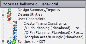
1) In menu Tools/PlanAhead - Pre-synthesis or
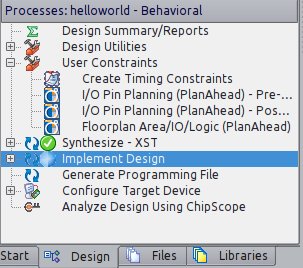
2) In the design windows, in User Constraints, just double click in I/O Pin Planning (PlanAhead) - Pre-synthesis
In both cases, it will ask you to create an UCF file. Accept it by clicking Yes.
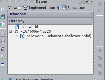
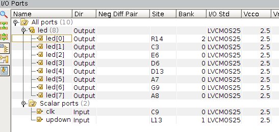
You'll note a new file helloworld.ucf, double clicking it will open PlanAhead. We can see all ports that we have declared before:
led(8) - output
clk - input
updown - input
Now it's time to assign pins to signals. In this board we have:
Led 0 - R14
Led 1 - C3
Led 2 - E6
Led 3 - D6
Led 4 - D13
Led 5 - A7
Led 6 - G9
Led 7 - A8
clock - C9
updown - L13 (switch SW0)
Here we can see in PlanAhead all pins assigned.
Note that we have again two options. Using PlanAhead we can click in the Site column and chose which pin to use or ISE, double click in Edit Constraints (Text) and type all constraints. Normally I assing one by PlanAhead and copy the rest in text mode which I think is faster.
Once done we can implement our design by clicking in Implement Design at Design tab in ISE.
Now it's time to generate our programming file by clicking in Generate Programming File (durrr). Once done, we click in Configure Target Device which will opens Impact. It will ask you to create a new project file, just click Yes.
Go to menu Edit/Launch Wizard. Select Configure devices using Boundary-Scan (JTAG) and select our helloworld.bit file. Bypass all 3 others devices. In the next window, check Pulse PROG, click in Apply and OK.

In the image above we can see that our FPGA is assigned with helloworld.bit and the others 3 device were bypassed. Now right-click over the green FPGA and select Program.
And it's done! (I really wish that your leds are blinking!!! LOL)